
 Thanks:
  Likes:


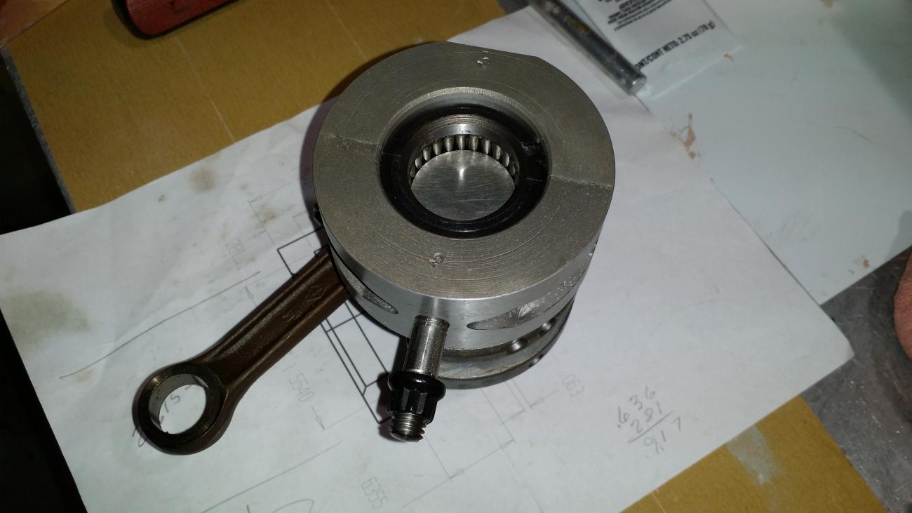
After a year in the making the three center main bearings have been completed. The first picture is a pair of 60-66 inch inline cranks. The first crank for the 6 cylinder in the Mark 75's had a single row of needles in the main. The later cranks had a double row of needles and used the same shell and rollers in all the inline 6's till the end of their production. The single land between the double row of needles and its clearance with the shell made the seal between the cylinders. A labyrinth type seal from the oil, like a reed block but without groves to hold more oil. That said, the old style crank had a double seal, two lands. To make the bearing work, I had to incorporate the lands in the bearing shell to make the seal and to retain the end play of the roller.
The process was to machine the bearing in one piece and heat treat. After they were heat treated the ends were ground to size. Then cleaned the OD by grinding to a common oversize OD. They were then chucked and the inside roller thrust faces were ground to the correct size. That would be the roller end play dimension. After those operations were completed, the bearings were cut in halve with wire feed EDM. Now we were able to chuck the halves, which had numbers etched in the ends so they were not switched or reversed, in a 6 jaw chuck on an ID grinder. By indicating on the ends to insure no step in the roller thrust face and indicating the OD to have the same readings, due to the appox .010 removed by cutting, at the cut line and 90 degrees for centering. The ID of the seal face and the ID of the bearing runway were ground to size. Long winded process. Now we were ready to grind the OD. For that process I made a mandrel to run in a center-less grinder. The end of the mandrel had a land turned to the shell roller surface size and rare earth magnets inserted 180 degrees apart. These locked the shell halves to the mandrel along with a cap on the end of the mandrel to clamp the shells against one of the roller thrust faces. This also reduced the possibility of the shell rotating on the mandrel. Turned the OD to size and cut groves in the OD for spiral lock rings.
I had concerns about the getting the spiral lock on the crank, but they threaded around like putting a key on a key ring. They will be placed on the crank first and then the loaded halves will be placed between them and then snapped around the bearing.
Was a long and trying process, but came out as I had hoped.

Bookmarks