Results 1 to 10 of 623

Thread: Building A looper Beast

Hybrid View

  1. #1
    Team Member R Austin's Avatar
    Join Date
    Aug 2005
    Location
    ludington Michigan
    Posts
    250
    Post Thanks / Like

    Default

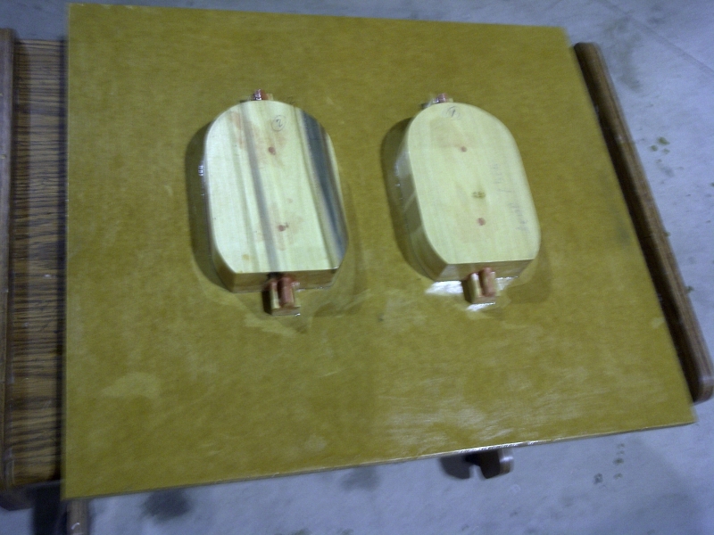
    With all that funny information I design a 3 piece head, as was the looper beast. Which is the most practical for molding and coring purposes. I will not use a head gasket, but a flanged sleeve with silicon o-rings. I do find it interesting that the Konig did not use anything but interference and per-matex for sealing. Which is what I did on the 6 rotary valve motor at the beginning of this piece. Worked fine. Mainly because it was a open wet sleeve and the head was also open. This allowed the bolts which were place in notches a the sleeve base to actually clamp the cylinder sleeve and the block perimeter by deforming the head to comply.

    Now a trailer ball of 1 8/7" size would make a good plug to create the chamber, except that they have a flat on the top. That's acceptable if I can find a ball with the right size flat. While walking thru the Wal Mart auto department a trailer ball in their rack caught my eye. It was a miss-machined ball that had been cut down to far on the blank making the base thin and you guessed it the flat on the top small. The size of a spark plug hole. I bought it.
    Name:  Head-106.jpg
Views: 10173
Size:  386.4 KBName:  Head-107.jpg
Views: 10039
Size:  322.6 KBName:  Head-108.jpg
Views: 10040
Size:  328.4 KBName:  Head-109.jpg
Views: 9950
Size:  335.4 KBName:  Head-110.jpg
Views: 9803
Size:  333.6 KB

  2. #2
    Team Member R Austin's Avatar
    Join Date
    Aug 2005
    Location
    ludington Michigan
    Posts
    250
    Post Thanks / Like

    Default

    Thanks to modern age computer and printing systems the need to allow for aluminum shrinkage is some what easier. Aluminum shrinks at a rate of 1/64 of an inch per inch in all directions. Therefore all dimensions to create a pattern must be raised to include that rate. You will see wood pattern parts with paper glued to their faces. These paper patterns have been printed from the cad drawing full size to reflect a 1:1.0156 ratio at printing. All pattern prints were created in this manner to cover shrinkage.

    Bondo is a great medium for fast pattern development as you see in many of the pattern making photos. Parts used a reverse pattern such as the trailer ball are painted with lite vegetable oil and plunged into the bondo to create the pocket. Removal as soon as the bondo takes a rubbery set, allows a few minutes window of time to trim excess material. It also allows easy sanding and shaping.

    The trailer ball was bored and an alignment pin was added to center and square it in the head. Because of the added material for machining the head surface and changing chamber size, the ball went into the wood pattern beyond the spring point of the ball which would create a back draft condition. To cure that problem I turned a band that had a ID of the 1 7/8 ball and turned the OD to form a chamfer at the surface and zero at the ball mid point. The ring had a flange that seated on the wood and continued to displace the Bondo to finish the chamber. The final casting has enough material to allow chamber sizes for both alcohol and gas.
    Name:  100 Inch Head cut a way from Block Side.jpg
Views: 10956
Size:  79.5 KBName:  100 Inch Head cut a way From Outside.jpg
Views: 11065
Size:  94.1 KBName:  100 Inch Head hidden line block side.jpg
Views: 9747
Size:  83.5 KBName:  100 Inch Head hidden line side.jpg
Views: 9697
Size:  47.8 KBName:  100 Inch Head Set 2.jpg
Views: 9578
Size:  81.1 KBName:  100 Inch Head Set.jpg
Views: 9629
Size:  85.4 KBName:  100 Inch Head w Coil Holders.jpg
Views: 10918
Size:  80.7 KB

  3. #3
    Team Member R Austin's Avatar
    Join Date
    Aug 2005
    Location
    ludington Michigan
    Posts
    250
    Post Thanks / Like

    Default

    My water core size was near double that of the Quincy. It is a split mold that is filled by air pressurizing the sand and blowing it into the mold. I Had 12 heads cast and made near 40 cores before getting my oven temp, mold air venting, time in mold and hand mold rotation correct to insure internal coverage right before I had enough cores for 12 pieces. That's correct, rotating a 450 degree mold by hand. The Quincy single side mold sure was easier to fill did not need rotation. Having 2 sides to the mold near doubled the water volume and still left adequate material around the chamber and the bolt bosses. I hope! That will really be a time prov-en test.Name:  Head-111.jpg
Views: 9715
Size:  411.9 KBName:  Head-112.jpg
Views: 9556
Size:  419.2 KBName:  Head-115.jpg
Views: 9466
Size:  384.1 KBName:  Head-116.jpg
Views: 9553
Size:  417.4 KB

  4. #4
    Team Member R Austin's Avatar
    Join Date
    Aug 2005
    Location
    ludington Michigan
    Posts
    250
    Post Thanks / Like

    Default

    On the first trial run of heads, the core had 4 posts that met the plug side of the head to insure positioning of the core and would be welded shut with a plug. They are eliminated in the final head allowing the heads and all other cast parts to go straight to heat treat to bring them to T6 state. The following pics are of a head that I sacrificed to ensure core position and wall thickness around the combustion chamber.
    Attached Images Attached Images           

  5. #5
    Team Member R Austin's Avatar
    Join Date
    Aug 2005
    Location
    ludington Michigan
    Posts
    250
    Post Thanks / Like

    Default

    On another head some combustion chamber machining to test the cutting tool. I will now build holding fixtures for the complete machining of another sacrificial head, after complete machining to drawings and a 21CC chamber. The next series will be drawing and pattern development of the mid case casting pattern.Name:  Head 122.jpg
Views: 2825
Size:  369.9 KBName:  Head 124.jpg
Views: 2765
Size:  470.6 KBName:  Head 125.jpg
Views: 2744
Size:  346.0 KB

  6. #6
    Team Member R Austin's Avatar
    Join Date
    Aug 2005
    Location
    ludington Michigan
    Posts
    250
    Post Thanks / Like

    Default

    Quote Originally Posted by R Austin View Post
    On another head some combustion chamber machining to test the cutting tool. I will now build holding fixtures for the complete machining of another sacrificial head, after complete machining to drawings and a 21CC chamber. The next series will be drawing and pattern development of the mid case casting pattern.Name:  Head 122.jpg
Views: 2825
Size:  369.9 KBName:  Head 124.jpg
Views: 2765
Size:  470.6 KBName:  Head 125.jpg
Views: 2744
Size:  346.0 KB

    Attached are more pics of the roughing in of the cylinder heads. 1 end and 1 mid head.

    Also I have attached the drawings produced for making the mid case half. After the design of the part, the sand mold form needed to be created. This actually is harder than a cylinder block for the looper. I spent many hours creating this mold in the computer. Trying to keep my head around what I was looking at and how to get it to pull apart in the right places. Looks like a simple drawing, but not so.Name:  IMG-20120901-00623.jpg
Views: 2825
Size:  366.1 KBName:  IMG-20120902-00624.jpg
Views: 2705
Size:  356.8 KBName:  IMG-20120902-00625.jpg
Views: 2705
Size:  318.9 KBName:  Inter Case Pattern 1.jpg
Views: 2708
Size:  112.2 KBName:  Inter Case Pattern 2.jpg
Views: 2704
Size:  85.7 KBName:  Inter Case Pattern 3.jpg
Views: 2975
Size:  84.9 KBName:  Inter Case Pattern 4.jpg
Views: 2700
Size:  75.9 KBName:  Inter Case Pattern 5.jpg
Views: 2810
Size:  78.8 KBName:  Mid Case0002.jpg
Views: 3266
Size:  72.7 KBName:  Mid Case0003.jpg
Views: 3155
Size:  71.2 KB

  7. #7
    Team Member
    Join Date
    Jul 2012
    Posts
    65
    Post Thanks / Like

    Default

    Just to cool!!!:d

  8. #8
    Team Member R Austin's Avatar
    Join Date
    Aug 2005
    Location
    ludington Michigan
    Posts
    250
    Post Thanks / Like

    Default

    The following will be pics of the construction of the pattern for casting the Mid Case. As previously mentioned, over sized paper patterns were glued to the wood for cutting. The 3rd dimension being height, was done by selecting the proper split point for drafting purposes, laminating wood and plane to the correct thickness, including shrinkage. Lots of small parts for making boxes from bondo to make many parts and the use of bondo for repeating cavities from a single model. The pics are sequenced as the construction proceeded.
    Attached Images Attached Images           
    Last edited by R Austin; 09-11-2012 at 02:55 PM. Reason: Spelling

Thread Information

Users Browsing this Thread

There are currently 45 users browsing this thread. (0 members and 45 guests)

Similar Threads

  1. Legendary Dub Parker's B Looper found!
    By Original Looper 1 in forum Outboard Racing History
    Replies: 6
    Last Post: 07-25-2022, 06:16 PM
  2. Quincy Looper Pictures and Collections
    By Original Looper 1 in forum Outboard Racing History
    Replies: 71
    Last Post: 01-21-2008, 04:26 PM
  3. Waldman F 44 Looper has been found!
    By Original Looper 1 in forum Outboard Racing History
    Replies: 26
    Last Post: 06-18-2007, 09:55 AM
  4. Quincy's 90 ci King Looper Beast
    By Original Looper 1 in forum Outboard Racing History
    Replies: 1
    Last Post: 04-06-2007, 07:08 AM

Bookmarks

Posting Permissions

  • You may not post new threads
  • You may not post replies
  • You may not post attachments
  • You may not edit your posts
  •