 Thanks:
  Likes:
 Block is coming along. a few pics of the mid case and block after cutting transfer runners. Set up and drilled and taped head bolt holes. Milled both ends of the engine assembly.
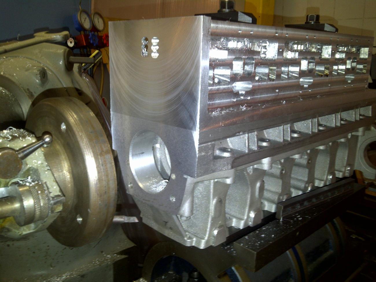


Block is coming along. a few pics of the mid case and block after cutting transfer runners. Set up and drilled and taped head bolt holes. Milled both ends of the engine assembly.
Having milled the ends of the block, I put a few bolts in to just sit the complete assembly vertical with a couple of heads in place. It is fitting up good. I received the cylinder sleeves a couple of days ago and talked to Wiseco a couple of times this week. Finally got the pistons on order and was given a by the end of the month delivery date. Will wait on the pistons before final fitting of the sleeves. I have left enough material on block to case and head surfaces and the case to block side of the mid case for final fitting. Will not commit without piston in hand and measuring. I have included pics of the new top main cap and the work progressing on the exhaust elbow. Should have them cast before pistons arrive. Will also rough in the cylinder bores with cylinder boring bar to within .060.

Are those heads thicker than the original Quincy heads?
I'm curious why you went with individual heads (vs. all 6 cyilinders at once, or at least 2 or 3 at once)? The block would be far more rigid that way, which was why engine designers went away from individal cylinder construction after World War One.
Jeff

I think there are three heads that have two chambers each . Likely much easier to cast 3 smaller heads than to pattern and cast a large single head . See post #45 ,jigging for a 6 cylinder would have been much more involved ,plus if something doesn't work out you've only messed up a two cylinder head . It's hard to imagine Dick messing up after following this inspiring build .

The block is more than rigid enough. Three heads V one offers an easier solution to a single cylinder mishap. In addition the shorter 2 cylinder heads will be less likely to warp. Many of the early engines were individual cylinders. A one piece head provided strength.Originally Posted by Fastjeff57

BTW: Bill Tenney's comment after seeing a Quincy Looper for the first time was, "It sure has a lot of head bolts"!
First question, yes they are thicker. The pic with the 2 heads partially bolted on after head bolts drilled, are the finished thickness. The head is thicker because it has to have a 21cc chamber vs 13cc and carries twice as much water. To keep the chamber area 50% of the cylinder area per Jennings and make a hemispherical chamber it is what it is.
It has three 2 cylinder heads. I did address in an early post that it was the most logical way because of the ease of pattern and core making. The whole motor is three 2 cylinder motors stacked. This engine unlike the smaller motors, pure deflectors, has equal center to center spacing. All machining setups are done from the center line of each pair. Get the numbers done for half and mirror it for the pair. Move the pair center to center and you do it again. One head casting makes all heads. The round end was made with a long connector tube so cutting off the end for the mid head was possible. The last I knew, Cummins 6 inline engines ran three 2 cylinder heads.
Making the block more rigid? I don't think a head can do much when you look at the front cover and the mid case. I do not think those two parts when bolted are letting the block go anywhere. The main bolts are cross bolted into the block along with the block flange bolts. I look at the stock motor with its little water cover and its intricately cast head and think it does not take much to hold the top on. It takes a lot of bolts with a head to keep the gasket from blowing.
Got the block cylinders roughed in to 2.998. Will take one hole out to a half thousands shrink on a 1/16 wall 2.875 sleeve that I have and warm the block and insert. Will then bore to 2.875 so I can load the crank and one rod/ piston assembly in that hole. That will let me get all my deck heights correct with the piston as received from Wiseco. Will then bore out sleeve and fit sleeves and re-deck all parts.
Boring aluminum with a cylinder boring bar has a totally different technique than boring a steel or iron sleeve. It takes a pointed end tool with a chip breaker point and a high rake.... And keep flooded with light weight motor oil or ATF to prevent tool heat and gumming of aluminum to tool.
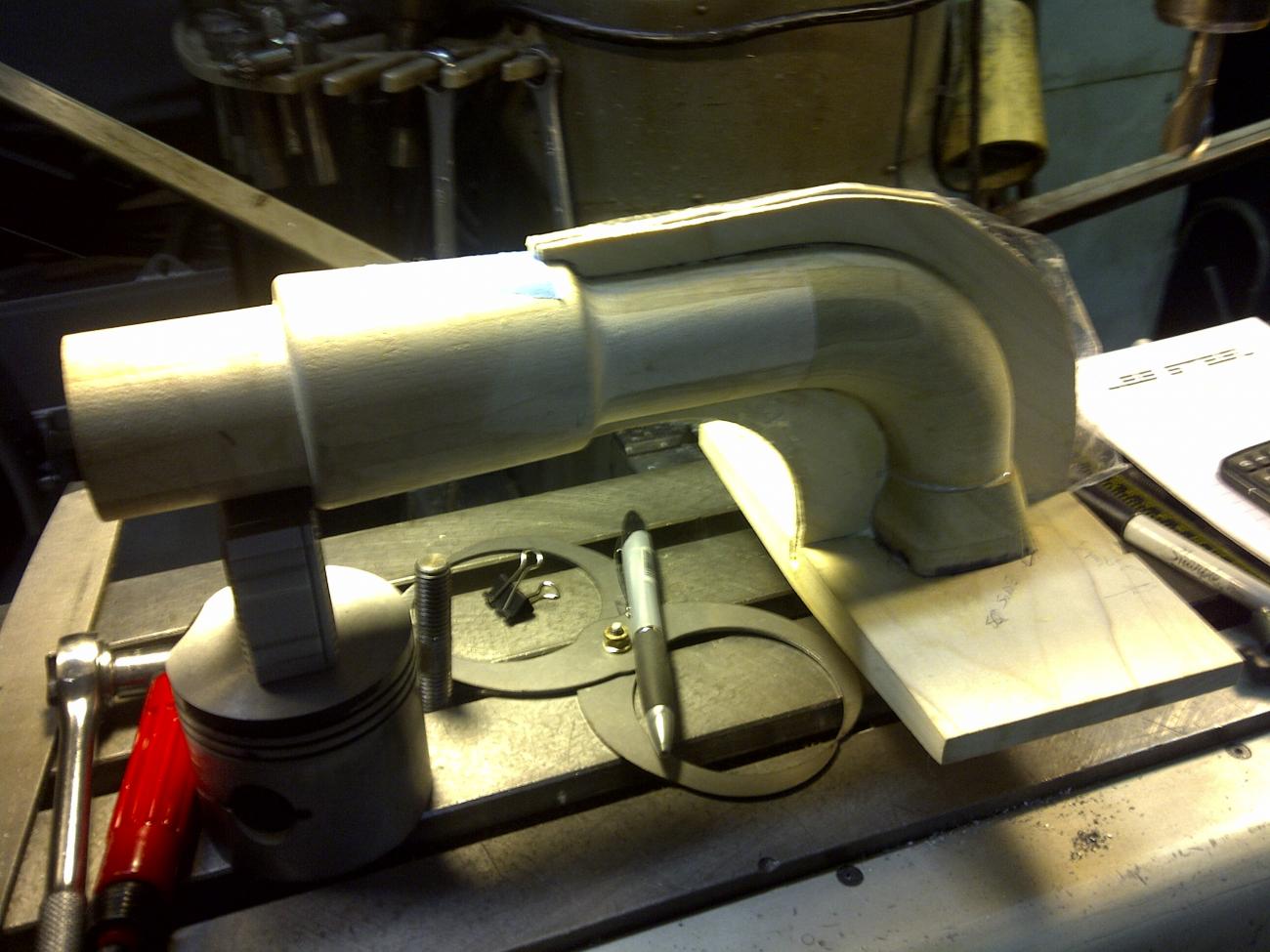
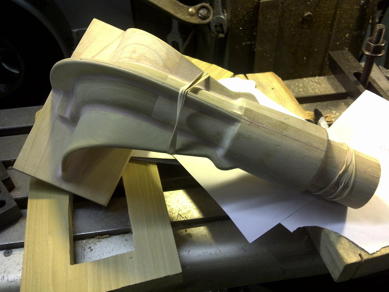
Exhaust elbow progressing along nicely. Hope to complete that this week and I have completed a top cap mold for the block water out cover. Should go to foundry first of next week.
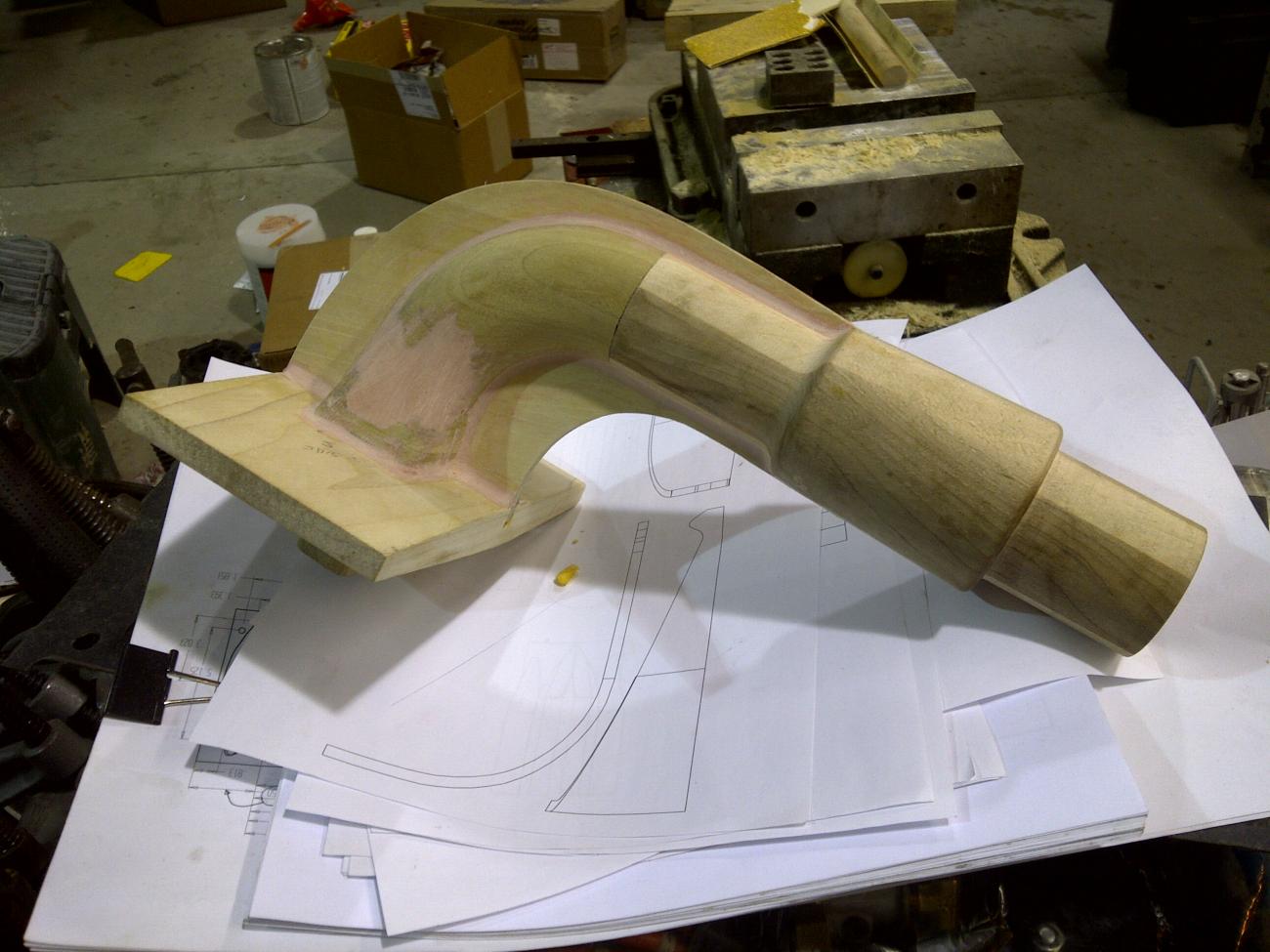
Finished the exhaust elbow pattern and the core for it is near completion. Just a few pics of the wood work. Not my favorite thing to do but just have to do it.
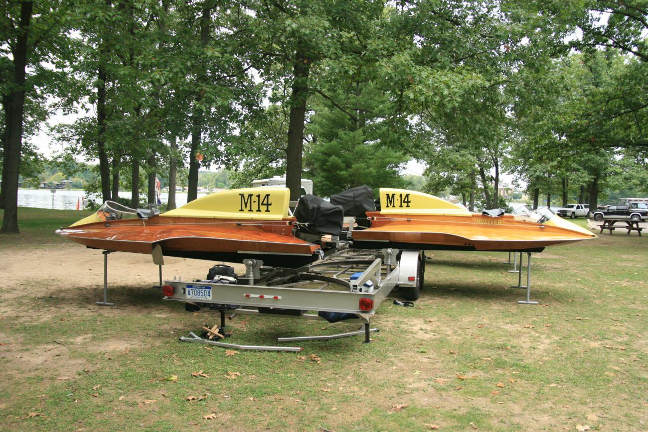
I quess I will take this opertunitity to plug my boat and trailer rig.
The first four pics are from Roar and Soar in 2010. The fourth pic is of my dad who looks forward to seeing the new motor run. I take him to the hanger some weekend days when he is up to it. He is now 90. He cretiques my work and keeps aksing if it is going to be to heavy.
The next four are a repair of the boat on the back, M-211. The skins were starting to peel off and leaked badly at Roar and Soar. So I removed and replaced them with some mods sent to me by Ron Jones. That took up all of the winter, spring and fall of 2011. Did not make any trips that year.
The last two were taken at Hillsdale last fall when we ran the 6 Looper. The M-211 is the M-14 on the rear of the trailer (left in pic) after completing the rebuild. I returned it to its original condition and number when new in 1966.
Attachment 53364Attachment 53365
There are currently 22 users browsing this thread. (0 members and 22 guests)
Posting Permissions


Bookmarks