Results 1 to 10 of 623

Thread: Building A looper Beast

Hybrid View

  1. #1
    Team Member R Austin's Avatar
    Join Date
    Aug 2005
    Location
    ludington Michigan
    Posts
    250
    Post Thanks / Like

    Default

    I guess that the question of how much parasitic drag there may have been from the dyno is now a real consideration. The issue with the chain failure is because the double row chain sprocket tooth center to center spacing on the drive shaft was not sufficient for the double row heavy duty chain. There were no disclaimers associated with the sprocket specs but it is not a fit. When I initially set up the chain I realized that the chain fit snug but did not realize that the chain was not bottoming in the sprocket roller pockets. I had ordered a heavy duty pre-stressed chain as a replacement only to be disappointed when received and realized that I had received a standard pre-stressed chain. When I installed the original HD chain, I had to shorten by four or five links. I took the new standard chain and laid in a spare sprocket to see how it looked and then took the left over HD chain and tried in the sprocket and realized how tight it felt. I took the links and drove them down into the sprocket. I could pick the sprocket up by just gripping the chain.


    Name:  20171020_142453.jpg
Views: 1196
Size:  118.1 KB


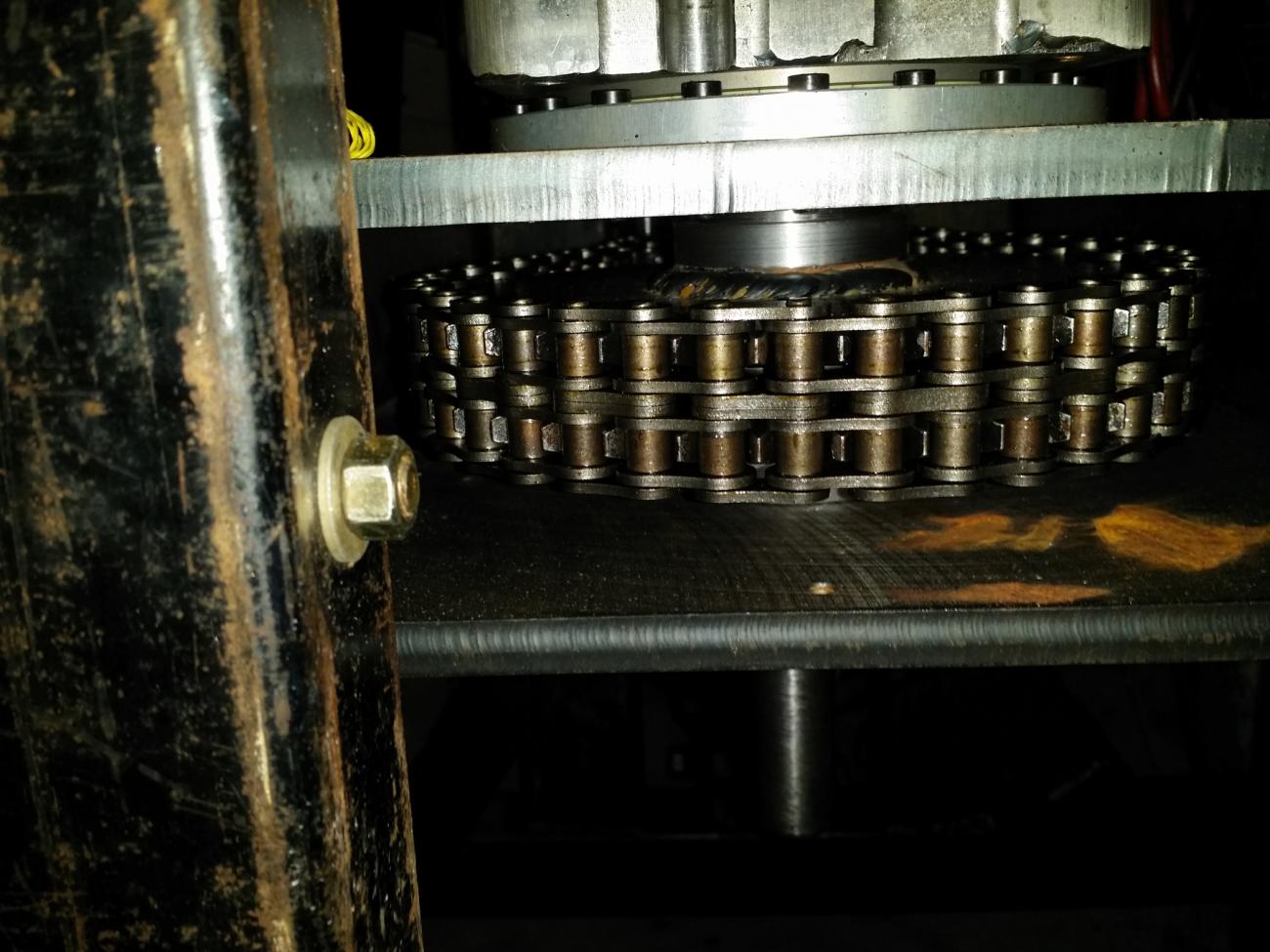
    I then went back to the failed chain and reexamined it looking at the area that would have been pinched by the lack of space between the two sprocket rows of teeth. As can be seen in the pictures that the chain center section links are burned brown and that the link segments adjacent to the teeth are pressure marked from being pinched. All of this heat energy of pulling the chain into and out of the sprocket and coming from the drive sprocket is energy that is not making it to the load sensor at the pump.


    Name:  20171020_142600.jpg
Views: 1202
Size:  107.9 KB


    Name:  20171020_142638.jpg
Views: 1160
Size:  112.0 KB


    Name:  20171020_142846.jpg
Views: 1193
Size:  117.9 KB


    The last 2 pics are of the drive and driven sprockets after I changed to the chain drive. You can see in the drive sprocket that the links are tight between the teeth and there is room at the outer sides of the teeth. The driven sprocket I welded from flat sprockets and my turned hub. Dual sprockets that large are not offered and need to be fabricated. That sprocket was welded with the HD chain as a spacing guide and can be seen in the picture that it has the right center to center spacing.


    Name:  20170117_170722.jpg
Views: 1190
Size:  144.0 KB


    Name:  20170117_170628.jpg
Views: 1186
Size:  140.3 KB

  2. #2
    Team Member
    Join Date
    Sep 2008
    Location
    Singapore/Melbourne/Italy
    Posts
    780
    Post Thanks / Like

    Default

    Perhaps one of those onshaft inline eddy current load cells might be an easier way to measure the output.
    They used them on one European offshore sterndrive class to allow a power to weight specification to be met so I know they are small.

  3. #3
    Team Member R Austin's Avatar
    Join Date
    Aug 2005
    Location
    ludington Michigan
    Posts
    250
    Post Thanks / Like

    Default

    Quote Originally Posted by Powerabout View Post
    Perhaps one of those onshaft inline eddy current load cells might be an easier way to measure the output.
    They used them on one European offshore sterndrive class to allow a power to weight specification to be met so I know they are small.
    Looked through out the internet and do not find any eddy current unit that will handle this kind of HP except large dyno units, let alone the one described in your post.

    After some research, it appears a 3 inch wide RPV Silent chain meets the HP requirements, although falls short of meeting the RPM range. That chain/sprocket set comes at a price of about $1400.00 dollars. We will see how the new double row chain holds up before that investment.

  4. #4
    Team Member
    Join Date
    Sep 2008
    Location
    Singapore/Melbourne/Italy
    Posts
    780
    Post Thanks / Like

    Default

    Quote Originally Posted by R Austin View Post
    Looked through out the internet and do not find any eddy current unit that will handle this kind of HP except large dyno units, let alone the one described in your post.

    After some research, it appears a 3 inch wide RPV Silent chain meets the HP requirements, although falls short of meeting the RPM range. That chain/sprocket set comes at a price of about $1400.00 dollars. We will see how the new double row chain holds up before that investment.
    OK I will try to find it. I do remember seeing an article about the supplier for Class 1 offshore a few years for the European racers. I was sure they said it was an eddy current device so it was the size of a ujoint.

    Shaft torque equipment is quite simple, 2 sensors on a shaft looking at each other and a known shaft material so when it twists it can be calculated on the fly.
    Something like this but the one I remember looked like 2 flanges together and bolted to the the Mercrusier tailstock shaft flanges.
    http://catalog.cooperinstruments.com...rque-load-cell

  5. #5
    Team Member
    Join Date
    May 2006
    Posts
    37
    Post Thanks / Like

    Default

    The land-and-sea dynamite dynamometer makes a great water brake, but they are pricey.

  6. #6
    Team Member R Austin's Avatar
    Join Date
    Aug 2005
    Location
    ludington Michigan
    Posts
    250
    Post Thanks / Like

    Default

    Quote Originally Posted by Powerabout View Post
    OK I will try to find it. I do remember seeing an article about the supplier for Class 1 offshore a few years for the European racers. I was sure they said it was an eddy current device so it was the size of a ujoint.

    Shaft torque equipment is quite simple, 2 sensors on a shaft looking at each other and a known shaft material so when it twists it can be calculated on the fly.
    Something like this but the one I remember looked like 2 flanges together and bolted to the the Mercrusier tailstock shaft flanges.
    http://catalog.cooperinstruments.com...rque-load-cell


    After reviewing the Cooper instrument site I believe that the unit that you are looking at is just a rotational load cell. Nothing that can be part of a rotating shaft assembly. IE, instead a load cell on the end the arm reading the pumps desire to spin, it would be mounted on the rotational end point of the pump and the other flange mounted to a stationary structure. It reads a twisting, rotational, load. None of the offerings are capable of applying a resistance load.

  7. #7
    Team Member
    Join Date
    Sep 2008
    Location
    Singapore/Melbourne/Italy
    Posts
    780
    Post Thanks / Like

    Default

    Quote Originally Posted by R Austin View Post
    After reviewing the Cooper instrument site I believe that the unit that you are looking at is just a rotational load cell. Nothing that can be part of a rotating shaft assembly. IE, instead a load cell on the end the arm reading the pumps desire to spin, it would be mounted on the rotational end point of the pump and the other flange mounted to a stationary structure. It reads a twisting, rotational, load. None of the offerings are capable of applying a resistance load.
    I wasnt looking for a friction brake just an easy way to measure torque on a spinning shaft.
    Perhaps using gears is a better way to get your 2:1 load?

  8. #8
    Team Member R Austin's Avatar
    Join Date
    Aug 2005
    Location
    ludington Michigan
    Posts
    250
    Post Thanks / Like

    Default

    I have noticed that some of the posts that I had trouble uploading pictures on have appeared again like they were copied over again. That is what really happened because at the time, as I tried, the system notified me that they had to clear a moderator. Not knowing what that meant I just approached the process differently and was successful. Now that Ron changed some of the rules, they popped up.

    Having said all that, "Is there anybody, Ron or anyone that can tell me how to backup or download the entire thread for safe keeping?"
    Thanks Master Oil Racing Team thanked for this post
    Likes Master Oil Racing Team liked this post

Thread Information

Users Browsing this Thread

There are currently 20 users browsing this thread. (0 members and 20 guests)

Similar Threads

  1. Legendary Dub Parker's B Looper found!
    By Original Looper 1 in forum Outboard Racing History
    Replies: 6
    Last Post: 07-25-2022, 06:16 PM
  2. Quincy Looper Pictures and Collections
    By Original Looper 1 in forum Outboard Racing History
    Replies: 71
    Last Post: 01-21-2008, 04:26 PM
  3. Waldman F 44 Looper has been found!
    By Original Looper 1 in forum Outboard Racing History
    Replies: 26
    Last Post: 06-18-2007, 09:55 AM
  4. Quincy's 90 ci King Looper Beast
    By Original Looper 1 in forum Outboard Racing History
    Replies: 1
    Last Post: 04-06-2007, 07:08 AM

Bookmarks

Posting Permissions

  • You may not post new threads
  • You may not post replies
  • You may not post attachments
  • You may not edit your posts
  •